A floor beam assembly system and method for installing floor beams within a structure are provided.
Aircraft floor beam shear diagram.
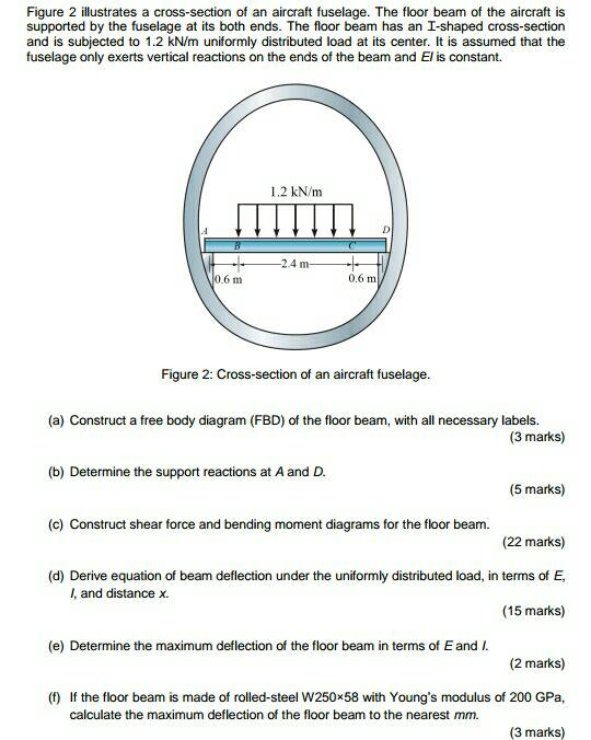
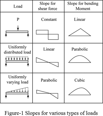
Shear and moment diagrams consider a simple beam shown of length l that carries a uniform load of w n m throughout its length and is held in equilibrium by reactions r 1 and r 2 assume that the beam is cut at point c a distance of x from he left support and the portion of the beam to the right of c be removed.
Us8240606 b2 by willard n.
According to one embodiment a floor beam assembly for installing a floor beam within a structure is provided.
Draw the shear and moment diagrams for this beam and loading condition.
When subjected to a structural load at its far unsupported end the cantilever carries the load.
Double overhanging beam aircraft draw the shear and moment diagrams bending moment and shear force diagram overhanging beam mathalino solution to problem 589 design forbending moment and shear force diagram for overhanging.
Free online beam calculator for generating the reactions calculating the deflection of a steel or wood beam drawing the shear and moment diagrams for the beam.
Introduction notations relative to shear and moment diagrams e modulus of elasticity psi i moment of inertia in 4 l span length of the bending member ft.
Simple beams applied load beam diagram free body diagram applied load note.
Typically it extends from a flat vertical surface such as a wall to which it must be firmly attached.
The loads applied to the beam from the roof or floor must be resisted by forces.
This illustrates only the diagrams with no actual calculations.
Like other structural elements a cantilever can be formed as a beam plate truss or slab.
As with the shear flow analysis the mathematics behind this calculation are complex and outside of the scope of this tutorial.
Select a beam and enter dimensions to get started.
Shear flow analysis on a simple box beam wing structure collapse moment analysis.
Constructing beam free body diagrams from a floor framing plan.
Then scroll down to see shear force diagrams moment diagrams deflection curves slope and tabulated results.
A free online beam calculator to generate shear force diagrams bending moment diagrams deflection curves and slope curves for simply supported and cantilvered beams.
Use this beam span calculator to determine the reactions at the supports draw the shear and moment diagram for the beam and calculate the deflection of a steel or wood beam.
Moment 44 145l ft lb max.
When there is no applied.
A cantilever is a rigid structural element that extends horizontally and is supported at only one end.